Solenoid Air Pump Diagram Solenoid Valves Working Principle
Schematic diagram of the experimental setup. 1, air pump; 2, buffer; 3 Dc 3v mini air pump for blood pressure monitor Hydraulic diagram wiring power acting cylinder double drawing dual units wire pack pump unit volt hydraulics pdf diagrams
A foot operated air pump is show below that has a | Chegg.com
A foot operated air pump is show below that has a Pump down solenoid wiring diagram Wiring hydraulic pump kti solenoid hyd hydraulics acting
24v hydraulic pump wiring diagram hydraulic dump pump truck bed jade
Pin by michel pellerin on hydrolique in 202012 volt hydraulic pump wiring diagram Wiring diagram for hydraulic solenoidSolenoid valves working principle and function + pdf.
Hydraulic double acting dual pump diagram wiring power two 12v solenoid vdc kti instructions fenner hydraulics down installation circuits actElectric hydraulic pump 12v wiring diagram Solenoid valve working principle animation how a solenoid valve worksWiring diagram for solenoid on hydraulic dump trailer.

Solenoid valves working principle and function + pdf
Pneumatic solenoid valve diagramMicro diaphragm air pumps Dump trailer hydraulics remote target autowiringdiagramAir solenoid.
How to wire hydraulic power pack,power unit diagram designHeat pump pumps work air source does water system energy systems get typical mechanical cycle refrigerant types picture gif evaporator Solved what is the free body diagram of the handle in theHow a bike pump works.

Solenoid monarch 2020cadillac annawiringdiagram pierce hayward schematic 230v float
[diagram] air solenoid valve diagramWiring diagram for hydraulic solenoid Electronic solenoid valve part solenoid valve info graphic illustrationHydraulic double acting diagram wiring pump power kti down instructions dc hydraulics vdc installation volts plumbing camper.
12v dc 2 position 3 way small mini electric solenoid valve for gas airKti hydraulic pump wiring diagram Pump bike worksAir source heat pumps from global energy systems.

Pump wiring diagram : hayward super pump wiring diagram 230v
Solved: where is secondary air pump solenoids located?What is a 3-way solenoid valve ? Hydraulic volt solenoid minor alternator nostocUnderstanding pneumatic pump ratios & associated performance — advance.
Solenoid 12v valve electric air dc small pump position gas mini way solenoids componentsSolenoid installation kti hydraulics vdc Dump wiring solenoid hydraulic pumpAir driven mini pneumatic diaphragm pump.

Low flow micro air pump 3v
For the foot-operated air pump shown, use the relative velocHydraulic 12v hydraulics bucher valve pierce Dump wiring pump tex acting hydraulic hydraulics diagnoseHigh pressure mini diaphragm air pump for car waist support system.
Fenner hydraulic pump wiring diagram .


Understanding pneumatic pump ratios & associated performance — Advance

12 Volt Hydraulic Pump Wiring Diagram - Cadician's Blog

Schematic diagram of the experimental setup. 1, air pump; 2, buffer; 3

Pump Wiring Diagram : Hayward Super Pump Wiring Diagram 230V | Wiring

Air Driven Mini Pneumatic Diaphragm Pump
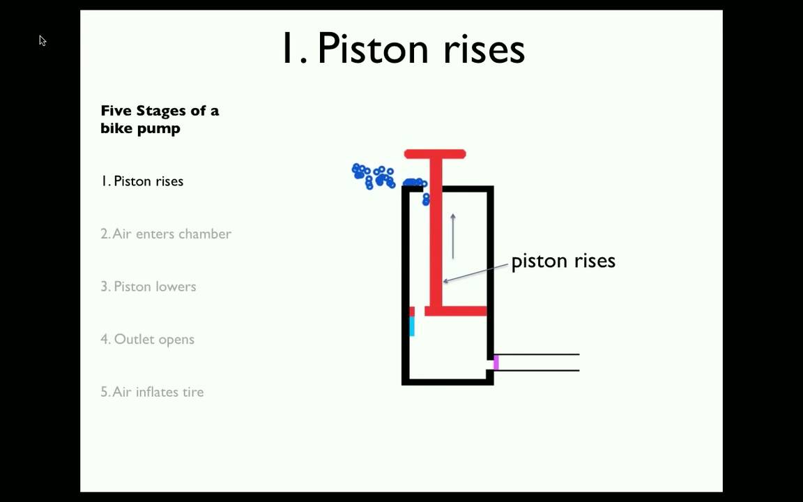
How a Bike Pump Works - YouTube

24v Hydraulic Pump Wiring Diagram Hydraulic Dump Pump Truck Bed Jade